|

|
Processed through Paypal No account required. |








Buy our over-priced crap to help pay the bills.



|
|
Processed through Paypal No account required. |
| Files | ||||
| File Name | Rating | Downloads | ||
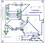 |
1ChipISO7816-V1 Programmer/Reader 1ChipISO7816-V1 Programmer/Reader FOR Educational Purposes Simple Full Features ISO 7816 Programmer and Reader board This device provides the capabilities for a Smart Card Programmer and Reader. This version uses a wide band Transistor Crystal Oscillator Clock circuit. This makes it easy to quickly change Crystal Clock frequencies for different Smart Card applications. Version V-3 uses a fixed frequency CMOS TTL Cryatal Oscillator module for clock requirements (Epson CMOS TTL Osc #SG-531P-3.579MC). Part Value Device Package Description B1 Bridge1A B-DIL B-DIL Bridge Rectifier C1 10UF P128-35 P128-35 Condenser 10uf 50V C2 10UF P128-35 P128-35 Condenser 10uf 50V C3 .1UF C2,5 C2,5-4 Condenser .1uf C4 100pf C2,5 C2,5-4 Condenser 100 pf C5 22pf C2,5 C2,5-4 Condenser 22 pf D2 1N4148 1N4148 DO35-10 Diode D3 1N4148 1N4148 DO35-10 Diode DL1 GRN LED5 LED5 LED Green DL2 RED LED5 LED5 LED Red IC1 MC1489 ... |
 |
9,990 | May 16, 2026 CadSoft |
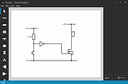 |
Circuit Diagram v3.1 Circuit Diagram v3.1 Design and share diagrams using a wide range of components. Easy to Use Design diagrams visually by placing components with your cursor. Modify their values using the properties editor. Export as Images Export your diagrams as images, either SVG or PNG. Plugins are available for additional formats. Includes all Common Components Symbols for most commonly-used components are included, from resistors and capacitors to logic gates and transistors. Custom Components Find many more components made by other Circuit Diagram users in the components section. Create your own for ones that haven't been made yet. Share Circuit Designs Browse circuits designed by others, and upload your own in the circuits section. Click here to visit the author's website. |
|
5,699 | Feb 28, 2023 Circuit Diagram |
 |
FlexBV5 Free v5.3162 FlexBV5 Free v5.3162 👉 Free cross-platform boardview viewer for electronics repair and analysis. FlexBV5 Free is a fast, native boardview viewer designed for electronics repair technicians, rework teams, and hobbyists who need a modern replacement for legacy boardview tools. Features: • Free edition for hobbyists and repair beginners • Modern SDL3-based interface • Cross-platform support for Windows, macOS, and Linux • Native decoding engine for multiple boardview formats • Supports legacy and generic boardview formats including .brd, .bdv, .bv, and .gr • Supports proprietary OEM formats including Asus FZ, Samsung CAD, Teboview, and XZZ PCB • Supports ODB++, GenCAD, Fabmaster, and Hyperlynx formats • Customizable retro and dark UI themes • High-DPI display support • Runs locally with no mandatory cloud login or telemetry Supported operating systems: • Windows 10, Windows 11 • macOS Catalina or higher • Linux x86_64 with glibc 2.31 or higher Supported languages: English Changes: v5.3162 07-27-26 * Updated fbvpdf schem viewer with performance improvements (search) * Updated fbvpdf to receive next/prev/goto commands from FlexBV * Updated FlexBV to handle more broken GenCAD exports 👉 This download is for the Windows 64bit version (very bottom of page). All other download assets are below: macOS: flexbv-free-5.3162-macos-universal.dmg Linux: flexbv-free-5.3162-linux-x86_64.tar.gz Click here to visit the author's website. |
|
1,815 | Sep 21, 2026 PLDaniels |
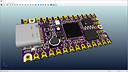 |
KiCad EDA v9.0.6 KiCad EDA v9.0.6 A Cross Platform and Open Source Electronics Design Automation Suite Schematic Capture KiCad's Schematic Editor supports everything from the most basic schematic to a complex hierarchical design with hundreds of sheets. Create your own custom symbols or use some of the thousands found in the official KiCad library. Verify your design with integrated SPICE simulator and electrical rules checker. PCB Layout KiCad's PCB Editor is approachable enough to make your first PCB design easy, and powerful enough for complex modern designs. A powerful interactive router and improved visualization and selection tools make layout tasks easier than ever. 3D Viewer KiCad's 3D Viewer allows easy inspection of your PCB to check mechanical fit and to preview your finished product. A built-in raytracer with customizable lighting can create realistic images to show off your work. About KiCad KiCad is an open source software suite for Electronic Design Automation (EDA). The programs handle Schematic Capture, and PCB Layout with Gerber output. The suite runs on Windows, Linux and macOS and is licensed under GNU GPL v3. Mission Statement The goal of the KiCad project is to provide the best possible cross platform electronics design application for professional electronics designers. Every effort is made to hide the complexity of advanced design features so that KiCad remains approachable by new and inexperienced users, but when determining the direction of the project and the priority of new features, the needs of professional users take precedence. Project Governance The KiCad project is governed by a technical committee made up of the members of the lead development team. Most decisions are made by a consensus of the technical committee. When a consensus cannot be reached the final decision is made by the project leader. History KiCad was first released in 1992 by its original author, Jean-Pierre Charras. It has been in continual ... |
|
2,694 | Nov 21, 2025 kicad.org |
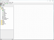 |
Logisim v2.7.1 Logisim v2.7.1 An educational tool for designing and simulating digital logic circuits, featuring a simple-to-learn interface, hierarchical circuits, wire bundles, and a large component library. As a Java application, it can run on many platforms. Features Design circuits using an intuitive graphical interface Watch the circuits be simulated as they are drawn Runs under Linux, MacOS X, and Windows Build circuits from truth tables using combinational analysis module This download is for the Windows version. If you need the MacOS version, download here. If you need the Linux version, download here. Click here to visit the author's website. |
|
4,008 | Feb 28, 2023 Carl Burch |
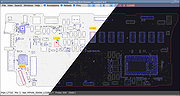 |
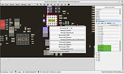
OpenBoardView v9.95.2 OpenBoardView v9.95.2 👉 Open-source boardview file viewer for electronics repair and diagnostics. OpenBoardView is a cross-platform open-source utility designed to load and display boardview files used in electronics repair. It allows technicians to visually inspect PCB layouts, search for components and nets, and trace signal connections without needing proprietary manufacturer tools. OpenBoardView supports a variety of boardview file formats commonly used for laptops, desktops, and other electronic devices, making it an essential tool for board-level troubleshooting and reverse engineering. Features: • View and navigate boardview files for PCB layouts • Search components by name, value, or reference designator • Highlight nets and trace signal connections • Cross-platform support with native builds • Zoom, pan, and layer visibility controls • Open-source and community-driven development • Supports multiple boardview formats including BRD and BVR Supported operating systems: • Windows 10, Windows 11 • macOS 10.15 or higher • Linux (64-bit distributions) Supported languages: • English Changes: v9.95.2 08-19-25 New features File formats XZZ PCB file format support (#309 #316 #334 d5099f9) Asrock PCBRepair Pro CAE file format support (#162 a8e9087) GenCAD: improve loading time (#321 6d63947) GUI Dynamic font scaling thanks to ImGui 1.92.0 (2d6105e, 99e3d90, 3249b9b, 3a89256) Windows high-DPI support (e238d63) Windows higher resolution application icon (3f98e11) macOS high-DPI support (9e9b367) macOS system menu bar and dock menu items to open new instance of OpenBoardView (19d90b8) Show configured keyboard bindings in Help→Controls dialog (653c39c) Add Save/Cancel buttons in Program preferences (b2e69e1) Apply font changes and user DPI scaling without restart (ee909a3) Build system Automatic development builds with Github Actions (#315) PDF Custom build of SumatraPDF for Windows updated to 3.5.2 Custom build of Evince for Linux updated to ... |
|
11,732 | Mar 01, 2026 openboardview.org |
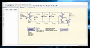 |
Qucs v0.0.19 Qucs v0.0.19 👉 Open-source circuit simulator for analog and digital electronics design and analysis. Qucs (Quite Universal Circuit Simulator) is an open-source electronics circuit simulator designed to perform circuit simulation using graphical schematic capture and a powerful simulation backend. It allows users to design circuits visually and analyze them with a wide range of simulation types including DC, AC, S-parameter, transient, harmonic balance, and noise analysis. Qucs features an intuitive graphical user interface for schematic entry, simulation setup, and result visualization. Simulation results can be displayed in various forms such as Cartesian, polar, Smith charts, tabular data, and timing diagrams. The software supports analog and digital components, RF simulation capabilities, and equation-defined devices, making it suitable for students, hobbyists, and engineers. Qucs uses SPICE-compatible simulation engines and supports netlist-based simulation, giving users flexibility in circuit analysis. It also includes optimization tools, parameter sweeps, and support for user-defined components and models. Features: • Graphical schematic capture with component library • DC, AC, transient, S-parameter, noise, and harmonic balance simulations • RF circuit simulation capabilities • Parameter sweeps and optimization tools • Equation-defined devices and custom models • SPICE-compatible netlist support • Data visualization including Cartesian, polar, and Smith charts • Tabular and timing diagram result display • Subcircuit and hierarchical design support • Cross-platform open-source application Supported operating systems: • Windows (XP, Vista, 7, 8, 10) • Linux • FreeBSD • macOS Supported languages: • English This download is for the Windows version (very bottom of page). If you need the macOS version, download here. Click here to visit the author's website. |
|
6,728 | Mar 01, 2026 Qucs team |
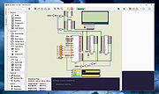 |
SimulIDE v1.1.0 SimulIDE v1.1.0 👉 Simple real-time electronic circuit simulator for students and hobbyists. SimulIDE is a simple real-time electronic circuit simulator intended for learning and experimenting with analog and digital electronic circuits and microcontrollers. It supports PIC, AVR, Arduino and other MCUs and MPUs, with a focus on speed, simplicity and quick testing rather than highly accurate professional circuit analysis. Features: • Real-time electronic circuit simulation • Analog and digital circuit support • PIC, AVR and Arduino simulation • Code editor and debugger • Arduino IDE 2 support • Support for GcBasic, PIC asm and AVR asm • Fast simulation with low CPU usage • Simple workspace for learning, testing and experimenting • Useful for students, hobbyists and electronics tinkerers • Source code available Supported operating systems: • Windows 64-bit, Windows 32-bit, Linux 64-bit, MacOS X86 Supported languages: English, Azerbaijani, Simplified Chinese, Czech, Dutch, French, German, Italian, Russian, Spanish, Portuguese, Brazilian Portuguese, Slovak, Turkish Changes: v1.1.0 03-12-26 Updated to SR2 (Stable Release 2). This download is for the Windows 64bit version (very bottom of page). All other download assets are below: Other Windows: SimulIDE_1.1.0-SR2_Win32.zip macOS: SimulIDE_1.1.0-SR2_MacOs.zip Linux: SimulIDE_1.1.0-SR2_Lin64.tar.gz Click here to visit the author's website. |
|
574 | Jun 14, 2026 santigoro |
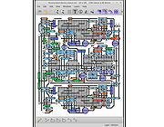 |
VeroRoute v1.96 VeroRoute v1.96 Cross-platform software for producing Veroboard (stripboard), Perfboard, and 1-layer or 2-layer PCB layouts. Automatically prevents short circuits and checks for open circuits. Built using the Qt library, and tested on Linux (32-bit and 64-bit) and on Windows 7 (32-bit and 64-bit). Pre-compiled versions available for Windows 7 (32 bit and 64 bit) and for 64-bit Linux Mint 18.3 (Cinnamon/MATE/Xfce/KDE). Features Cross-platform Veroboard and PCB modes Interactive auto-routing Connectivity checking & visualisation Import netlist from a TinyCAD, gEDA, or KiCad schematic , or specify the netlist graphically Switch instantly between Fat, Thin, Curved, and Vero track styles Easily create PCB designs with ground-fill Save output as PNG image or PDF 1:1 scale PDF output suitable for toner-transfer based PCB creation Gerber export for easy 1-layer or 2-layer PCB manufacture Create Bill of Materials and export it Component editor In-built tutorial This download is for the Windows64bit version. If you need the Windows 32bit version, download here. If you need the Linux 64bit version, download here. Click here to visit the author's website. |
|
4,295 | Feb 28, 2023 Alex Lawrow |
| Showing rows 1 to 9 of 9 | Showing Page 1 of 1 | 1 |
OlderGeeks.com Copyright (c) 2026
